
Alternative Cooling Solutions for High Power Optoelectronic
Paper details
Section titled “Paper details”| Field | Value |
|---|---|
| Journal | IMAPSource Proceedings |
| Published | 2026-07-14 |
| Authors | Michael Leers, Hans Schmidt, Philipp Imgrund |
| DOI | 10.4071/001c.165061 |
Supplier figures cited in the paper put diamond composites at up to 600 W/mK, up to 50% better than pure copper. Those conductivity values were supplier announcements, not measurements from this study. The study instead compared measured and modeled heat sink thermal resistance, expansion matching, and cooling-fluid behavior.
Package cooling starts with expansion mismatch
Section titled “Package cooling starts with expansion mismatch”Common high-power diode laser packages use a copper heat sink and indium soft solder. Copper has a coefficient of thermal expansion (CTE) of 16.8 ppm/K, while GaAs laser bars have a CTE of about 6.7 ppm/K. The authors identify this mismatch as an inherent source of mounting stress.
Water cooling is required above 100 W optical output. Common microchannel designs use deionized water at 0.5 l/min, where corrosion and erosion shorten heat sink life. For less than 50 W of thermally dissipated power per bar, the authors prefer conductively cooled heat sinks.
Thermal resistance came from coupled optical and wavelength measurements
Section titled “Thermal resistance came from coupled optical and wavelength measurements”Total thermal resistance is the temperature rise from the hottest bar point to the reference temperature divided by dissipated thermal power. The reference is the heat sink bottom for conduction or the inlet water temperature for active cooling. The hottest point is at the front facet in the waveguide.
Thermal power was calculated from optical output and operating voltage as functions of drive current. Junction temperature came from emission wavelength. Each bar needed its wavelength drift factor, while the slope of wavelength against lost power supplied the thermal power relation.
Tests used bars with 1.2 mm, 2.5 mm, and 4 mm resonators. Thermal resistance remains geometry dependent because heat spreads through three dimensions. Larger contact areas and different filling factors can change the value, so the paper gives no simple cross-design equation.
Integrated expansion matching improved conductively cooled packages
Section titled “Integrated expansion matching improved conductively cooled packages”Conventional expansion matching often adds a WCu or AlN submount. This adds a mounting step and degrades the thermal path. Fraunhofer ILT instead inserted molybdenum into copper, producing a CTE below 9 ppm/K and thermal resistance below 1 K/W.
The authors then used a silicon carbide diamond composite with copper layers. This design reached a CTE of 7 to 8 ppm/K and a thermal resistance of 0.7 K/W. They described it as expansion matched and thermally equal to or better than standard pure copper.
The mounting surface remains exacting. Bars have a 30% filling factor, a 500 µm pitch, and a 3 to 5 µm epitaxial layer. Typical specifications call for flatness below 1 µm, roughness Ra below 50 nm, and a front edge radius below 1 µm.
The nickel and gold plating provides corrosion protection and a solderable surface. The solder layer is 4 to 7 µm, and the p-side-down laser bar has a roughly 5 µm overhang to keep solder off the front facet.
Reported results span several cooling concepts.
| Heat sink design | Test or use condition | Thermal resistance |
|---|---|---|
| Copper microchannel | Above 100 W optical output; 0.5 l/min; 1 bar | About 0.3 K/W |
| Macrochannel | 50 to 60 W thermal per bar; 0.5 l/min at lower pressure | 0.5 K/W |
| Copper with integrated molybdenum | Conduction below 50 W thermal per bar | Below 1 K/W |
| ScD with copper layers | Conduction below 50 W thermal per bar | 0.7 K/W |
| ILasCo with AlN core | 1.2 mm bar; 0.5 l/min | 0.55 K/W, measured |
These values use different heat sinks and bar conditions, so the table indicates tradeoffs rather than a direct ranking.
Water-cooled designs traded pressure drop against erosion
Section titled “Water-cooled designs traded pressure drop against erosion”The required internal cooling structure has a wall heat transfer coefficient above 80,000 W/m²K. Typical microchannels measure 200 by 300 µm. The stated operating point is 0.5 l/min at a 1 bar pressure drop.
Macrochannels lower wall heat transfer and pressure drop while still moving 0.5 l/min. The reported thermal resistance is 0.5 K/W, and the authors place this approach at 50 to 60 W thermal power per bar. The paper links the lower flow velocity to reduced erosion.
Protective coatings can slow corrosion, but erosion can open defects where electrochemical corrosion accelerates. The authors used CFD to find turbulence and dead water regions. They then used PIV on an acrylic model to check local velocity and flow direction. PIV used laser-lit particles and short strobe images. New designs were simulated before fabrication and checked again afterward.
ILasCo isolated the water circuit with an AlN core
Section titled “ILasCo isolated the water circuit with an AlN core”ILasCo uses an AlN ceramic core and top and bottom direct copper bonded Cu/AlN structures. Selected copper and AlN thicknesses give a CTE of about 7 ppm/K, close to the GaAs value of 6.7 ppm/K. The ceramic core electrically isolates the water circuit. It permits non-deionized water, and the authors state that erosion and corrosion can be neglected in the ceramic channels.
After machining, the heat sink is about 3 mm thick, 22 mm wide, and 39 mm deep. Each copper layer is 300 µm thick. CFD showed homogeneous flow through all microchannels and no dead water near the laser bar.
The modeled thermal resistance fell 15% for a 2.5 mm bar when flow rose from 0.2 to 0.5 l/min. For a 4 mm bar, the reduction reached 30%. At 0.5 l/min, moving from a 1.2 mm to a 4 mm resonator reduced thermal resistance by nearly 50%. A mounted 1.2 mm bar measured 0.55 K/W at 0.5 l/min. A measurement confirmed the 2.5 mm model at 0.5 l/min.
Micro metal injection molding addressed complex near-net shapes
Section titled “Micro metal injection molding addressed complex near-net shapes”Micro metal injection molding can make complex, near-net-shape parts for mass production above 1000 pieces. The process blends fine metal powder into feedstock, injects the shape, debinds it, and sinters it. The paper’s powders had mean particle diameters below 5 µm, with adjusted binder, debinding, and sintering conditions.
WCu and MoCu were considered because copper provides conductivity while tungsten or molybdenum lowers CTE. Their limited miscibility caused sintering problems, and earlier parts often reached less than 95% of theoretical density. Fine powders improved initial homogeneity. Nearly full density required about 30 vol.% copper for at least some formulations.
The reported accuracy and physical properties were described as satisfying, without numerical tolerances. Corrosion resistance under process conditions still needed study. A low-cost joining method was also needed because micro metal injection molding cannot form the internal cooling structure in one piece.
Package selection remains geometry dependent
Section titled “Package selection remains geometry dependent”The cooling choice depends on dissipated power, bar geometry, flow rate, and package size. The paper places conduction below 50 W thermal power, macrochannels at 50 to 60 W, and water cooling above 100 W optical output. The limits use different power definitions, so they cannot define one continuous threshold.
Thermal resistance values should not rank designs without matching the bar geometry and operating point. Heat generation area, filling factor, resonator length, and three-dimensional heat flow all affect the result.
The authors suggest that diamond composites could replace water-cooled heat sinks, but the cited conductivity values were not verified here. ILasCo removes the need for deionized water and provides expansion matching, but it has a larger footprint than conventional copper microchannel heat sinks. Its 0.55 K/W result is above the roughly 0.3 K/W reported for copper microchannels.
Longer service life was the main design target, but the paper gives no quantified lifetime test. The remaining evidence concerns thermal resistance, flow behavior, material expansion, and prototype manufacturability.
Materials and support
Section titled “Materials and support”The ScD conductively cooled heat sink needs a diamond-composite heat spreader with a 7 to 8 ppm/K CTE. 6CCVD’s diamond materials catalog lists MPCVD-grown single-crystal and polycrystalline diamond plates and wafers, which are base-material candidates rather than the ScD composite itself. The composite lay-up, expansion matching, and mounting tolerances would need review through engineering support before a material is specified.
View Original Abstract
The market for high power diode lasers is still growing very fast (more than 10% a year). New applications are developed permanent and the range besides telecommunication, automobile and medical industries is rising rapidly. Because of the bright facilities of high power diode lasers plenty of niche applications also benefit from the high efficiency of the semiconductors. The interests in the R&D departments of diode laser industries have changed in the last years. Not the maximum of the emitted optical power out of the array is the main focus of the investigations anymore. The lifetime of the package is the critical value of the high power diode laser bars. A lot of R&D projects are focused on this issue. Common packages use a copper heat sink and Indium soft solder for mounting the laser bar. In the field of high power applications (> 100 W optical output power) water cooled heat sinks are necessary. In combination with the needed deionized water and high flow rates (0.5 l/min) corrosion is hard to prevent. Therefore, new cooling techniques are needed. In the last 12 months a lot of new solutions to increase the lifetime of the high power diode laser packages have been developed. Basically the new solutions are divided into two groups. One is using new high performance materials, especially diamond composites. Their thermal conductivity is announced with up to 600 W/mK depending on the suppliers. This heat spreading material has a thermal conductivity which is up to 50% better than pure copper and will replace water cooled heat sinks. The other is using new materials combinations for their active cooled heat sink instead of copper. New heat sink designs are possible because of new fabrication techniques like selected laser melting or μ-metal injection molding.
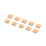
Diamond Heat Spreader With Copper Coated Metalized Surface
View Specs →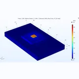
Advanced Thermal Simulation Service Diamond Heat Spreader Performance Analysis
View Specs →