
Cooling performance of top-side polycrystalline diamond integration in RF-power N-polar GaN high-electron-mobility transistors predicted using a robust modeling platform
Paper details
Section titled “Paper details”| Field | Value |
|---|---|
| Journal | Journal of Applied Physics |
| Published | 2026-03-17 |
| Authors | Dat Q. Tran, Rohith Soman, Jeong-Kyu Kim, Mohamadali Malakoutian, Srabanti Chowdhury |
| DOI | 10.1063/5.0304824 |
| Citations | 1 |
TCAD simulations predict a 33% peak temperature reduction from a 500 nm top-side PCD heat spreader on a 70 nm N-polar GaN RF HEMT. The comparison uses a 20 V supply and 0.65 A/mm quiescent bias. At 94 GHz and 25 dBm input, output power rises from 8.2 to 11.4 W/mm, while power gain rises from 2.9 to 4.3 dB. Peak PAE rises from 33% to 58%, and the bias-point peak temperature falls from 295 °C to 197 °C. These are TCAD predictions, not direct measurements of the PCD-integrated RF transistor.
Electrothermal model for high-field transport
Section titled “Electrothermal model for high-field transport”The platform couples a scattering-based electron mobility model to a 3D electrothermal device model in Silvaco Atlas. Low-field mobility combines acoustic phonon, polar optical phonon, remote charge, and interface roughness scattering. Field-dependent drift velocity is fitted to Monte Carlo results for AlGaN/GaN HEMTs. Hall measurements on N-polar structures with 5 to 12 nm GaN channels provide the temperature-dependent reference for the mobility calculation.
The model reproduces those Hall measurements across temperature while varying channel thickness. The fitted low-field mobility reaches 1550 cm²/Vs at 300 K when interface roughness scattering is weak. The simulated RF device has stronger roughness scattering and a low-field mobility of about 700 cm²/Vs at 300 K. That value is below the reported 850 to 1000 cm²/Vs for as-grown N-polar HEMTs with 8 to 12 nm channels. Interface roughness matters because the studied layer stack uses an 11 nm GaN channel. The mobility model supplies temperature- and field-dependent transport to the coupled heat calculation.
Thermal model and experimental calibration
Section titled “Thermal model and experimental calibration”The thermal test device includes the same PCD integration and a 500 nm diamond layer grown at 700 °C by microwave plasma chemical vapor deposition. The authors assign the 500 nm layer a thermal conductivity of 360 W/mK to represent boundary phonon scattering. This is below the reported 638 to 1000 W/mK for a 2 μm PCD layer with large grains and high sp³ phase purity.
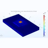
Layer conductivities and interface thermal resistances were taken from literature references. The simulation fixes the substrate bottom edge at 300 K and makes the sidewalls adiabatic. A factor of 1.5 scales every layer conductivity to account for three-dimensional lateral heat spreading. The factor is calibrated with a 400 μm thermal test structure. Simulated gate temperature closely matches measurements from the PCD-integrated device, and the simulated current-voltage curve also agrees with measurement. The matching 50 nm SiN-passivated device could not receive a separate thermal calibration because relevant data were unavailable.
Heat generation and two thermal regimes
Section titled “Heat generation and two thermal regimes”Heat generation follows Joule heating, with local power equal to current density multiplied by electric field. Both quantities peak beneath the gate on the drain side, where the thermal hotspot forms. In the thermal test device, peak temperature rises superlinearly with dissipated power. The peak electric field is nonlinear with drain bias in the quasi-linear current region, but follows drain bias in saturation. The two regimes meet near a 13 V knee voltage, while peak current density remains nearly linear across the bias range.
The authors relate the thermal nonlinearity to local electric field and channel conductance. Their model predicts that the temperature nonlinearity decreases as the inverse square of channel conductance. This explains the difference between the thermal test device and the scaled RF transistor. The RF device has a 70 nm gate, a 400 nm source-drain spacing, and a 100 nm gate-source spacing. Its knee voltage is about 1.5 V, corresponding to 2.5 to 3 W/mm dissipated power. Its higher conductance keeps the temperature rise nearly linear over the investigated power range.
At zero gate bias, the PCD-integrated device lowers peak temperature by about 30% at 3 W/mm and 37% at 15 W/mm. The same comparison raises drain current by about 14% at 5 V. These DC results connect the heat-flow improvement to the electrical response of the scaled device.
RF power performance
Section titled “RF power performance”Large-signal analysis used transient current responses in a load-line circuit at 94 GHz. Three supplies of 6, 12, and 20 V were tested with varied input amplitude and a class-AB quiescent gate bias of 0.65 A/mm. Each device used an optimized load-line resistance. The PCD device needed a smaller resistance because its saturation current increased and its knee voltage shifted.
The table reports Pout and GT at 25 dBm input, peak PAE from each power sweep, and peak temperature at the DC bias point.
| Supply voltage | Metric | SiN device | PCD device | PCD change |
|---|---|---|---|---|
| 6 V | Pout, W/mm | 2.9 | 3.8 | 31% higher |
| 6 V | PAE, % | 21 | 32 | 52% higher |
| 6 V | GT, dB | -1.7 | -0.45 | 30% higher |
| 6 V | Tpeak, °C | 129 | 96 | 26% lower |
| 12 V | Pout, W/mm | 4.7 | 6.7 | 43% higher |
| 12 V | PAE, % | 28 | 50 | 79% higher |
| 12 V | GT, dB | 0.5 | 2.0 | 41% higher |
| 12 V | Tpeak, °C | 207 | 138 | 31% lower |
| 20 V | Pout, W/mm | 8.2 | 11.4 | 39% higher |
| 20 V | PAE, % | 33 | 58 | 76% higher |
| 20 V | GT, dB | 2.9 | 4.3 | 38% higher |
| 20 V | Tpeak, °C | 295 | 197 | 33% lower |
PCD raises peak transconductance by 14% while total gate capacitance rises about 5% because of the thick diamond layer. Peak fT improves slightly, but peak fmax falls about 8%. The model attributes the fmax reduction mainly to increased gate-drain feedback capacitance.
The performance gain is not purely thermal. The authors identify quiescent bias, device-specific load-line resistance, and use of peak PAE as other major influences. At 0.55 A/mm, about 30% of saturation current, the SiN simulation reaches 283 °C at 20 V. PCD lowers that peak by 36% and raises Pout by 35%, GT by 34%, and PAE by 40%. At 25 dBm input, the SiN simulation gave 9.7 dBm output, 4.9 dB gain, and 50.5% peak PAE.
Model limits and device engineering implications
Section titled “Model limits and device engineering implications”A key material uncertainty is PCD thermal conductivity. The paper states that grain size and sp³ phase content prevent a standard conductivity value for a 500 nm layer. The reported 638 to 1000 W/mK applies to a 2 μm layer, so it cannot be assigned directly to the thinner simulated layer. Device selection should therefore use conductivity for the delivered film and include its interface thermal resistance.
The thermal model assumes temperature-independent conductivity for each thin epitaxial layer. It also uses a fixed 300 K bottom boundary, adiabatic sidewalls, and the 1.5 conductivity scaling factor. These assumptions define the predicted operating temperatures. SiN power sweeps were in reasonable agreement with an experimental reference, but the 94 GHz PCD performance is projected.
For material selection, top-side PCD offers a path around the low-conductivity AlGaN back barrier, which impedes vertical heat flow. The electrical penalty must remain part of the design. A 500 nm PCD layer adds capacitance, and the model shows an 8% fmax reduction despite the lower peak temperature. Engineers must balance peak temperature and output power against feedback capacitance and RF gain.
Materials and support
Section titled “Materials and support”The paper requires MPCVD-grown polycrystalline diamond as a 500 nm top-side heat spreader for channel-all-around cooling of N-polar GaN RF HEMTs. The diamond materials catalog includes MPCVD-grown polycrystalline diamond with thicknesses from 0.1 to 500 micrometers, which covers the required 500 nm film. Device-specific fabrication can be discussed through engineering support.
View Original Abstract
This study evaluates the cooling performance of top-side polycrystalline diamond (PCD) integration as an advanced thermal management strategy for N-polar GaN high-electron-mobility transistors (HEMTs) in high-power and radio-frequency (RF) electronics, using technology computer-aided design (TCAD). We constructed a robust mobility model based on well-established scattering theory and incorporated it into our device simulations, allowing reliable characterization of thermal effects and accurate projection of device performance under extreme conditions such as high temperatures and high electric fields. Large-signal power-sweep simulations of 70-nm GaN HEMTs integrated with a 500-nm PCD layer, operating at 94 GHz with applied voltages up to 20 V and bias currents of approximately 650 mA/mm, reveal a peak temperature reduction of 33%. The applied thermal management enables an increase of 39% in output power (Pout), 38% in power gain (GT), together with a 76% improvement in power-added efficiency (PAE). Our findings also reveal a superlinear increase in peak temperature with dissipated power, governed by the local electric field at the hotspot and the channel conductance. This behavior provides new physical insights into heat generation and thermal transport in GaN HEMTs.
Advanced Thermal Simulation Service Diamond Heat Spreader Performance Analysis
View Specs →
Electronic Grade Intrinsic Diamond Epitaxial Wafer H Terminated Superior 100 Mosfet Ready Substrate
View Specs →
Diamond Heat Spreader With Copper Coated Metalized Surface
View Specs →References we cover
Section titled “References we cover”Citing papers we cover
Section titled “Citing papers we cover”Original source
Section titled “Original source”References
Section titled “References”- 2002 - AlGaN/GaN HEMTs-an overview of device operation and applications [Crossref]
- 2020 - A review of technologies and design techniques of millimeter-wave power amplifiers [Crossref]
- 2025 - Integration of top-side low-temperature diamond on AlGaN/GaN RF HEMT for device-level cooling [Crossref]
- 2022 - Thermal Management of Gallium Nitride Electronics
- 2017 - Impact of recess etching on the temperature-dependent characteristics of GaN-based MIS-HEMTs with Al2O3/AlN gate-stack [Crossref]
- 2005 - A modified transferred-electron high-field mobility model for GaN devices simulation [Crossref]
- 2020 - Phonon-boundary scattering and thermal transport in AlxGa1−xN: Effect of layer thickness [Crossref]
- 2022 - Thermal conductivity of AlxGa1−xN(0≤x≤1) epitaxial layers [Crossref]
- 2024 - Characterization and modeling of the mobility, threshold voltage, and subthreshold swing in p-GaN gate HEMTs at cryogenic temperatures [Crossref]